
Workplan: Tool change position (Turning)
Last change: Sep 5, 2019
A position (X / Z) for the tool change is defined in the settings of the work plan (and, if necessary, in the work step "Clamping"). This position refers to the calculated cutting tip and is pre-assigned with X150 / Z150 on delivery.
However, this process is problematic in the case of a small working space and when changing between external and internal turning tools (or drills):
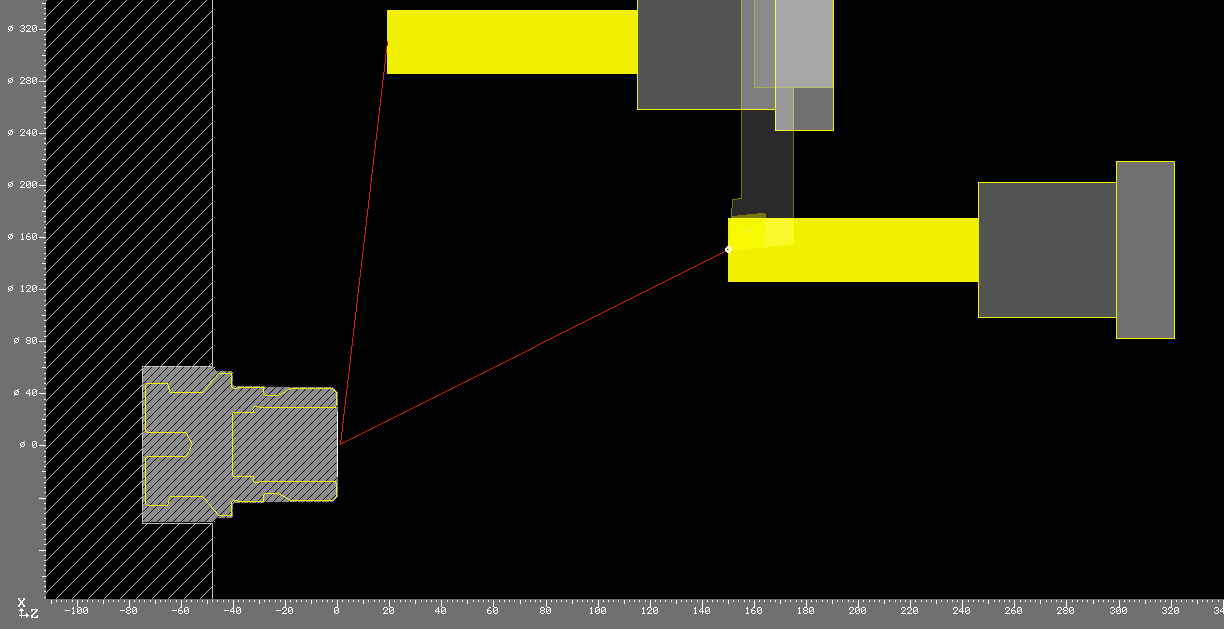 Picture 1: Pprevious tool external turning tool, shown semi-transparent, is followed by a solid drill. The solid drill moves very far into Z after machining and possibly hits the limit of the working space.
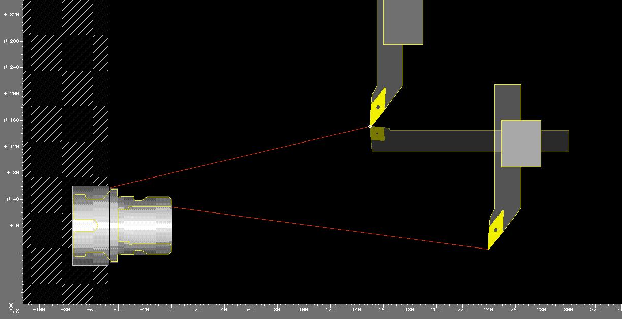 Picture 2: Previous tool internal turning tool followed by an external turning tool. The starting point of the external turning tool is possibly even below the center of rotation. If, however, the value for the tool change point in X were to be increased accordingly, then again a work space injury threatens in X when the outer turning tool is moved back to the change position.
As a solution to this problem, it is possible to approach the tool change point with the tool carrier reference point instead of the cutting tip.
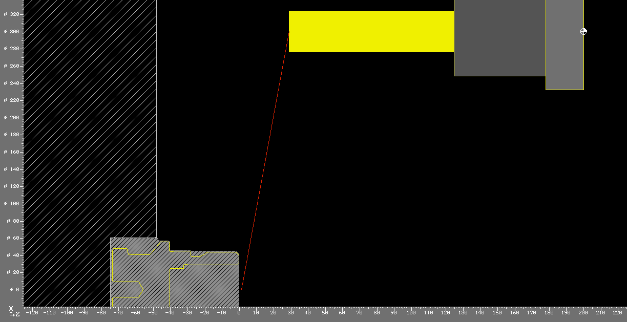 Picture 3: The position of the tool change then depends solely on the tool carrier reference point. Using the drill, start point and end point of the machining are identical, so that the start and end point of the cutting tip are identical.
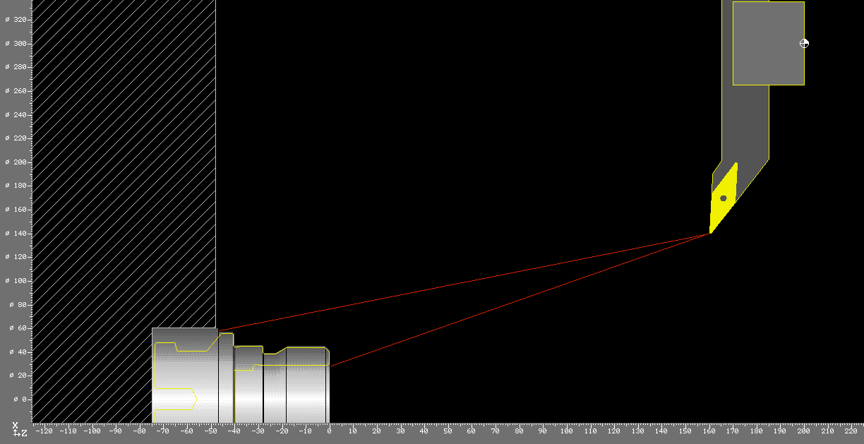 Picture 4: See picture 3 above. The tool carrier reference point has the identical position, the position of the cutting edge is of course much smaller in X and larger in Z compared to the drill.
The minimum values for the tool change point are specified by the longest tool (drill length) or by the tool with the largest radial extent plus workpiece radius, plus the safety distance, of course.
For the example above, the coordinates X300 / Z200 were chosen. The comparison with pictures 1 and 2 shows that you can get by with less space.
Disadvantage of this solution: Since the movement to the tool change point is output as a "normal" G0 block for the cutting edge, afterwards there are "crooked" target coordinates in the program that result from the tool change point and the setting dimensions of the respective tool. (There is no chance for the postprocessor to output a T4 D0 or T0400 or G53 here.)
This is how it's done:
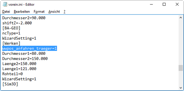
- Open the file vorein.ini in the main directory of the user data (% appdata%/KELLER KELLERplusDE/DATASD) with any text editor (e.g. Notepad).
- In the section [Werken], write the following line* and then save the file again. wwpos_anfahren_traeger = 1
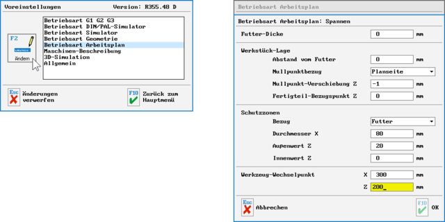
- Start the software and adjust the X / Z values for the tool change point in the default settings. F8 Setup > F4 System Configuration> F1 Preferences > Mark "Operating Mode Workplan" > F2 Modify > F3 Clamping > Tool Change Position X300 Z200 (for example)> 3 x F10 to accept the changes
* Attention: Please note that this setting applies to all work plans created in the future with this setting and vice versa NOT applies to all previously created work plans.